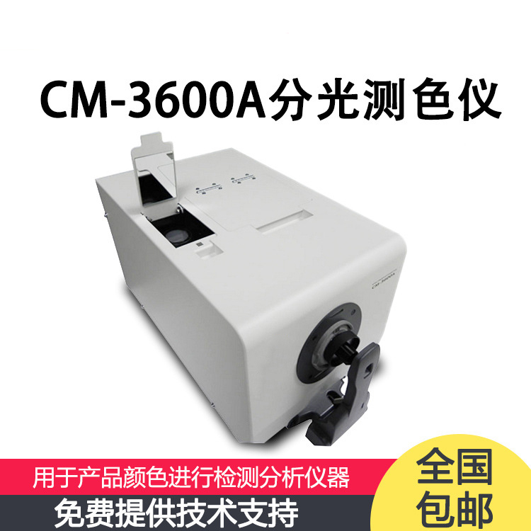
Analysis of common faults of cr400 / cr410 color difference
Cr400 / cr410 colorimeter is a colorimeter product introduced by Japan imported from Japan. Users often encounter problems such as light source error, correction failure, and failure to connect to the upper computer when using it. The following will bring solutions to common failures of cr400 / cr410 colorimeter.
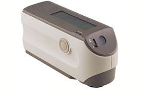
Difference between CR-400 and cr-410 colorimeters:
The main differences between Japan CR-400 and cr-410 are "lighting, photosensitive optical system" and "measuring diameter / Lighting diameter".
Lighting and photosensitive optical system
CR-400 is D / 0 (diffusion illumination vertical photosensitive mode) (JIS z8722 / including positive and negative light is executed).
Cr-410 is a vertical photosensitive mode of large area diffusion illumination.
Measuring diameter / Lighting diameter
CR-400 is Φ 8mm / Φ 11mm.
Cr-410 is Φ 50mm / Φ 53mm.
Common faults of cr400 / cr410 colorimeter and solutions:
1. How can Japan cr400 / cr410 colorimeter change the light source?
In order to change the light source of Japan cr400 / cr410 colorimeter, the initial setting of the measurer is required.
The initial setup can be done as follows.
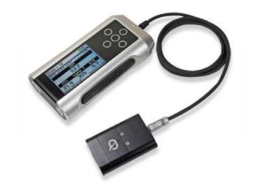
• connect dp-400 for initial setting. (please refer to CR-400 operation manual)
• connect CR-400 application software for initial setting. (please refer to the user manual of application software)
• connect to the color management software spectramagicnx for initial setting.
Select instrument - set instrument - instrument initialization menu.
As soon as the initial setting is carried out, the setting of the instrument will return to the initial state, and the measurement data and white correction data will be deleted.
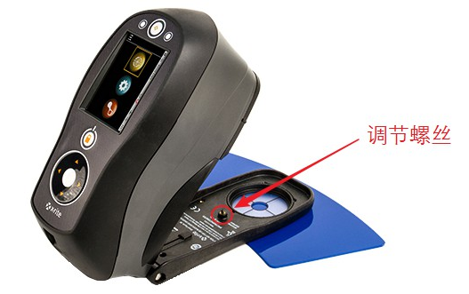
2. As soon as cr400 / cr410 colorimeter is white corrected, ER11 will be displayed.
ER11 is correction error.
The white correction may not have been carried out according to the correct procedure.
Please use the cleaned white correction plate to carry out the white correction again.
(for example) if you correct with something black, ER11 will appear.
If the corrective operation is normal, it may be a product failure. Please consult the business office.
3. When the color management software spectramagicnx is used, it cannot be connected with CR-400.
Please confirm the following.
• confirm whether the RS-232C cable is connected correctly.
When using USB conversion cable, please use it to connect RS-232C cable and computer.
Confirm whether "PC mode" is displayed on the CR-400 display screen.
Dp-400 confirms whether "remote control mode" is displayed on the display screen.
* if it is not shown, please refer to the following pages of the user manual for switching mode.
CR-400: < switch to PC mode >
Dp-400: < switch to remote control mode >
Confirm that the communication conditions of CR-400 and computer are the same.
The baud rate of dp-400 is fixed at 19200.
For CR-400, please refer to p27-28 "LCD, communication and other related settings" in the user manual.
In the communication settings of spectramagicnx, confirm whether the COM port connected to CR-400 has been selected.
< confirmation method >
Select communication settings from the measurer menu bar.
Display the set serial port dialog box to confirm that the COM port of CR-400 is selected on the COM port.
* if the COM port of CR-400 is not selected, please select it from the list of COM ports.
When using the USB conversion cable, please confirm the COM port according to the following methods.
Select device manager from the hardware tab, expand ports (COM and LPT), and the COM port number assigned to the USB conversion cable will be displayed.
When using the USB conversion cable, please confirm the COM port according to the following methods.
From the start menu, choose control panel, choose system.
Select device manager from the hardware tab, expand ports (COM and LPT), and the COM port number assigned to the USB conversion cable will be displayed.